Youtube

Advancing the Science of Ultrasound Guided Regional Anesthesia and Pain Medicine

Greater Occipital Nerve Block

Introduction

Greater occipital nerve (GON) block is often performed to ameliorate different types of chronic primary headache (headaches on > 15 days per month) including occipital neuralgia, cervicogenic, migraines and cluster headaches. This involves a local anesthetic injection with or without steroid.

Both landmark and ultrasound guided approaches have been described for GON block. The classical landmark technique involves an injection medial to the palpated occipital artery at the level of the superior nuchal line. In comparison, the ultrasound guided technique is more target specific thus the results are more favourable as demonstrated in a number of clinical studies.

Anatomy

The GON is the sensory branch of the posterior ramus of the second cervical (C2) spinal nerve. Together with the lesser occipital nerve, the GON innervates the skin of the occipital region up to the top of the head (vertex).

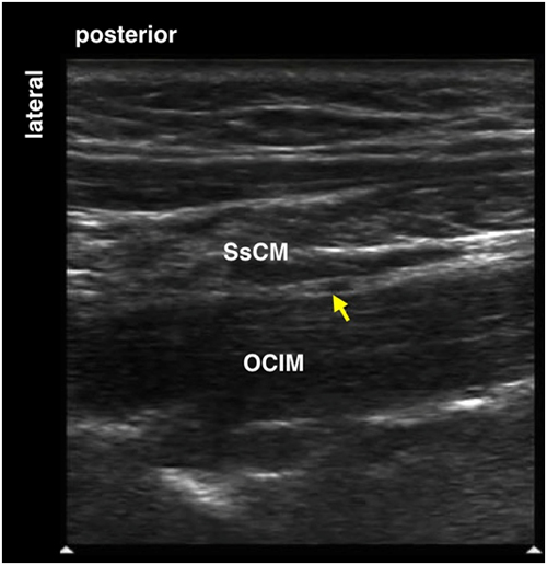
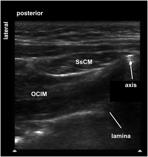
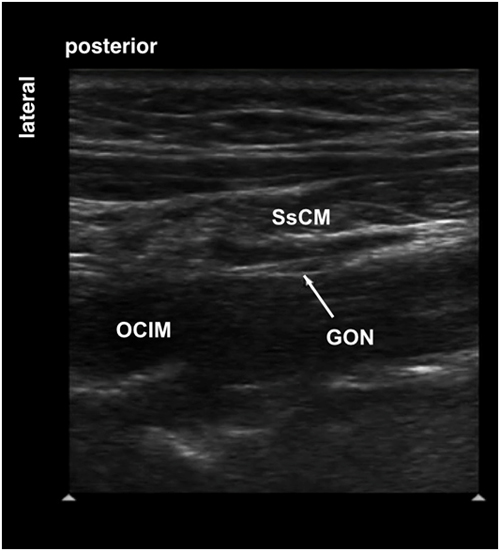
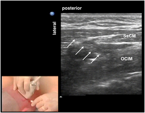
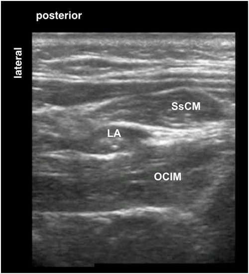
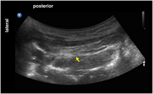
After leaving the C2 spinal nerve posterior to the lateral atlanto-axial joint, it travels inferiorly and laterally to appear at the inferior border of the obliquus capitis inferior muscle (OCIM). The GON travels in a fascial plane between the OCIM and the semispinalis capitis muscle (SsCM) as it ascends on the posterior surface of the OCIM before it pierces (SsCM). The GON terminates as a superficial nerve by either piercing the upper part of the trapezius muscle or running through the tendinous arch between the trapezius muscle and the sternocleidomastoid muscle, where it lies medial to the occipital artery.

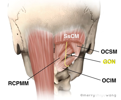
The suboccipital triangle is formed by three muscles, the obliquus capitis inferior muscle, the obliquus capitis superior muscle and the rectus capitis posterior major muscle (Figure 1).

Figure 1. Anatomy of the right suboccipital triangle in the posterolateral aspect of the neck

GON = greater occipital nerve
OCIM = obliquus capitis inferior muscle
OCSM = obliquus capitis superior muscle
RCPMM = rectus capitis posterior major muscle
SsCM = semispinalis capitis muscle

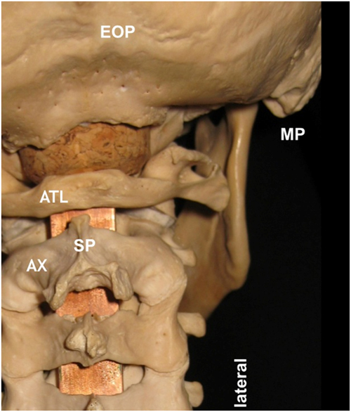
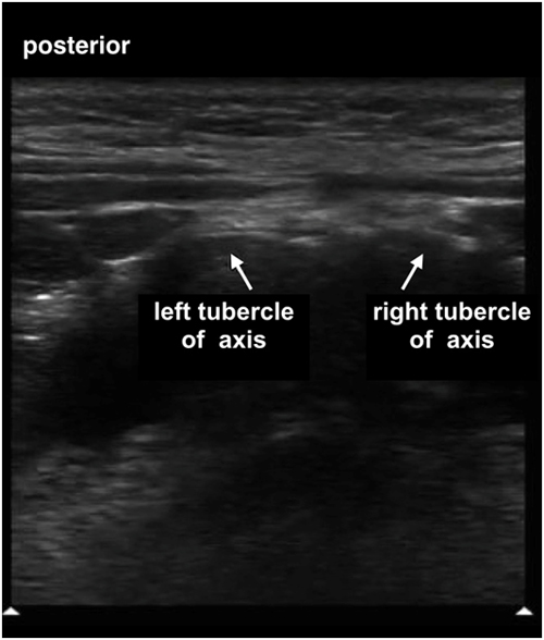
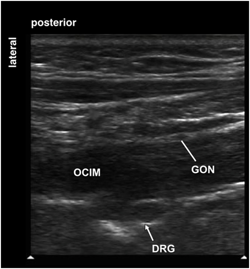
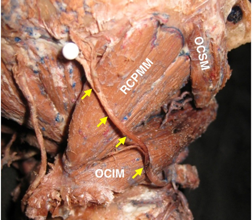
The OCIM is the important deep muscular landmark for localizing the GON. The right OCIM spans from the spinous process (right tubercle) of the axis (C2) medially to the transverse process of the atlas (C1) laterally (Figure 2).The RCPMM spans from the spinous process (SP) of the axis to the lateral part of the inferior nuchal line of the occiput.

The OCSM spans from the transverse process of the atlas to the occiput, slightly superior and lateral to the inferior nuchal line (Figure 2).

Figure 2. Cadaver specimen showing the right suboccipital triangle in the posterolateral aspect of the neck with the semispinalis capitis muscle removed

yellow arrows = greater occipital nerve
OCIM = obliquus capitis inferior muscle
OCSM = obliquus capitis superior muscle
RCPMM = rectus capitis posterior major muscle

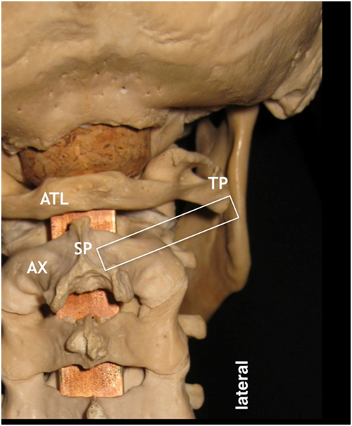
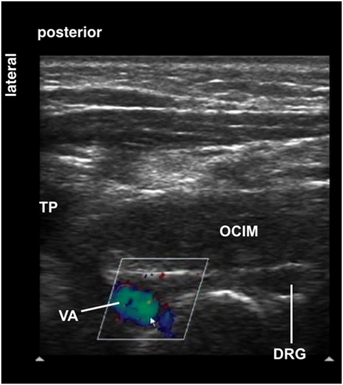
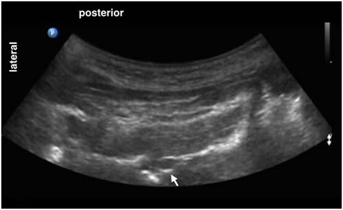
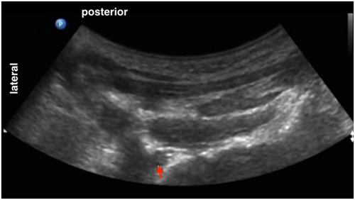
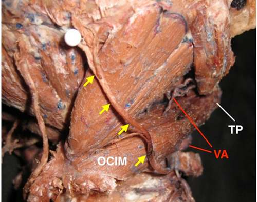
It is important to recognize the vertebral artery (VA) when performing GON block. Before entering the suboccipital triangle, the VA is located anterior to the OCIM at this level and is in close proximity to the transverse process (TP) of the atlas. Note that the VA is significantly lateral to the GON (Figure 3).

Figure 3. Location of the vertebral artery relative to GON

yellow arrows = greater occipital nerve
OCIM = obliquus capitis inferior muscle
TP = transverse process of the atlas
VA = vertebral artery

After ascending through the foramen transversarium of C1, the vertebral artery reaches the suboccipital triangle (upper red open arrow) and passes through a groove over the posterior arch of the atlas before entering the foramen magnum.

Sonoanatomy

In the transverse sonographic view, the hypoechoic GON is seen sandwiched between the semispinalis capitis muscle (SsCM) posteriorly and the obliquus capitis inferior muscle (OCIM) anteriorly (Figure 4).

Figure 4. A transverse sonogram showing the greater occipital nerve

yellow arrows = greater occipital nerve
OCIM = obliquus capitis inferior muscle
SsCM = semispinalis capitis muscle

Scanning Technique

  • Position the patient prone.
  • After skin and transducer preparation, place a linear high frequency 10-12 MHz transducer on the skin surface to obtain a best possible transverse view of the GON (Figure 5). Note that a transducer with a larger footprint or a convex transducer can offer an expanded field of view in this area (see comments in clinical pearls).

Figure 5. A linear transducer positioned oblique on the back of the neck

  • Optimize machine imaging capability by selecting the appropriate depth of field, focus range, and gain.
  • Position the transducer (represented by the white rectangle) slightly oblique with the medial end pointing towards the spinous process of the axis (recognized by it's prominent bifid appearance) and the lateral end pointing towards the transverse process of the atlas (Figure 6).

Figure 6. Optimal transducer (white rectangle) position shown on a skeleton

ATL = atlas
AX = axis
SP = spinous process of axis
TP = transverse process of atlas
White rectangle = transducer position

Nerve Localization

A number of palpable external landmarks are helpful for scanning and nerve localization (Figure 7).

They are:

  1. the external occipital protuberance (EOP); this is the starting point of a systematic scanning
  2. the inferior border of the mastoid process; this is approximately where the lateral end of the transducer should orient (the final transducer position is often slightly caudad to this bony landmark)
  3. the spinous process of axis (C2) when palpable; this is where the medial end of the transducer should orient

Figure 7. External bony landmarks helpful for nerve localization

ATL = atlas
AX = axis
EOP = external occipital protuberance
MP = mastoid process
SP = spinous process of axis

A number of internal sonographic bony, muscular and vascular landmarks help to localize the GON.

The bony landmarks are:

  1. the occiput with the sonographic prominent EOP;
  2. the posterior arch of the atlas (with no spinous process); and
  3. the axis with its big bifid spinous process.

The muscular landmarks are:

  1. the obliquus capitis inferior muscle (OCIM); and
  2. the semispinalis capitis muscle (SsCM).
  • The vascular landmark is the vertebral artery which is lateral to the GON and anterior to the lateral part of the OCIM.
  • A neural landmark, the second dorsal root ganglion, is medial to the vertebral artery and anterior to OCIM.
  • Perform a systematic anatomical survey from cephalad to caudad starting in the midline.
  • First place the transducer in the back of the head to capture a transverse view of the occiput with the external occipital protuberance (EOP) in the midline (Figure 8 and Figure 9).

Figure 8. Transducer placed in the back of the head to visualize the external occiput protuberance


Figure 9. Posterior transverse view showing the occiput and external occiput protuberance in the midline with its bony shadow below and subcutaneous tissue above

EOP = external occipital protuberance
  • Then move the transducer slowly caudad to capture a transverse view of the posterior arch of atlas below the occiput (Figure 10). Note that the atlas has no spinous process. This is the first bony structure encountered below the occiput.

Figure 10. A posterior transverse view of the atlas in the midline and its bony shadow below

  • Then move the transducer further caudad to the C2 level. The axis has a characteristically prominent bifid spinous process with left and right tubercles (Figure 11 and Figure 12).

Figure 11. Transducer moved further caudad to visualize the axis with the characteristic bifid spinous process


Figure 12. A posterior transverse view of the axis (C2) in the midline with a bifid spinous process

  • Once identified the spinous process of axis, move the transducer laterally to visualize the obliquus capitis inferior muscle (OCIM) that is a distinct muscle posterior to the lamina of the axis and anterior to the semispinalis capitis muscle (SsCM) (Figure 13 and Figure 14).
  • Note that the transducer is now oriented slightly oblique with the lateral end of the transducer pointing more cranially towards the inferior part of the palpable mastoid process (Figure 13).

Figure 13. Transducer oriented oblique with the lateral end pointing cranially towards the mastoid process


Figure 14. Transverse sonogram showing the axis, obliquus capitis inferior muscle and semispinalis capitis muscle

OCIM = obliquus capitis inferior muscle
SsCM = semispinalis capitis muscle
  • Move the transducer further laterally along the width of the OCIM. The spinous process of axis is no longer in view.
  • Now identify an oval shaped hypoechoic structure sandwiched between the SsCM and OCIM. This is the GON (Figure 15).

Figure 15. A posterior transverse view showing the hypoechoic GON between SsCM and OCIM

GON = greater occipital nerve
OCIM = obliquus capitis inferior muscle
SsCM = semispinalis capitis muscle
  • Deep (anterior) to the OCIM is another round hypoechoic structure which is the second dorsal root ganglion (DRG) (Figure 16).

Figure 16. A posterior transverse view showing the hypoechoic dorsal root ganglion (DRG) anterior to the OCIM

DRG = the second dorsal root ganglion
GON = greater occipital nerve
OCIM = obliquus capitis inferior muscle
  • Continue to move the transducer laterally (Figure 17) and follow the OCIM laterally to locate the vertebral artery as confirmed by Color Doppler (Figure 18).
  • Note that the vertebral artery (blue on Color Doppler due to transducer angle) is anterior to OCIM (Figure 18).
  • Continue to scan laterally to identify insertion of OCIM to the transverse process of atlas.

Figure 17. Transducer is moved further lateral to locate the vertebral artery


Figure 18. Color Doppler showing the vertebral artery lateral to the dorsal root ganglion and insertion of OCIM to the transverse process

DRG = the second dorsal root ganglion
OCIM = obliquus capitis inferior muscle
TP = transverse process of atlas
VA = vertebral artery

Movie 1. Steps to localize the greater occipital nerve

Needle Insertion Approach

  • Ultrasound guided GON block is considered an intermediate skill level (level II) block. This is performed with the patient prone or sitting, head in neutral position and neck flexed.
  • Place the transducer in a slightly oblique plane at the C2 level to capture a transverse view of the OCIM slightly lateral to the spinous process of axis.
  • Identify the hypoechoic GON structure sandwiched between the OCIM and SsCM.
  • Distinguish the GON from the second dorsal root ganglion which is deeper (anterior to OCIM).
  • Using the hydrolocation technique, insert a 5 cm 22 G needle in-plane in the lateral to medial direction and aim to position the needle tip in the plane between OCIM and SsCM (Figure 19).

Figure 19. Needle advanced from lateral to medial to approach the GON

arrows = block needle
OCIM = obliquus capitis inferior muscle
SsCM = semispinalis capitis muscle

Movie 2. Needle advancement towards GON

Local Anesthetic Injection

Use hydro-dissection to confirm fluid distention in the correct plane before injecting 2-4 mL of local anesthetic around the GON (Figure 20).

Figure 20. Local anesthetic spread in the plane between the semispinalis capitis muscle and obliquus capitis inferior muscle

LA = local anesthetic
OCIM = obliquus capitis inferior muscle
SsCM = semispinalis capitis muscle

Clinical Pearls

Use of a Low Frequency Transducer

If appropriate, use a low frequency curved transducer to capture a wide field of view in the region to visualize the OCIM in its entirety. The attachment of this muscle to the axis on the medial end and to the transverse process of the atlas on the lateral end can be appreciated.

The GON is often seen despite using a low frequency transducer (Figure 21).

Figure 21. Low frequency transducer to view the greater occipital nerve

arrow = greater occipital nerve

Movie 3. Low frequency transducer scanning


The second dorsal root ganglion is seen deep (anterior) to the OCIM (Figure 22).

Figure 22. Low frequency transducer to view 2nd dorsal root ganglion

arrow = the second dorsal root ganglion

The vertebral artery is seen more laterally (Figure 23).

Figure 23. Low frequency transducer to view the vertebral artery more laterally

arrow = vertebral artery

Video Gallery

Selected References

  • Walker J, Howell S. Ultrasound guided greater occipital nerve blocks for post-traumatic occipital neuralgia. W V Med J 2014;110:12-3.
  • Ultrasound-guided greater occipital nerve blocks and pulsed radiofrequency ablation for diagnosis and treatment of occipital neuralgia. 2013;3:256-9.
  • Cho JCS, Haun DW, Kettner NW. Sonographic evaluation of the greater occipital nerve in unilateral occipital neuralgia. J Ultrasound Med 2012;31:37-42.
  • Narouze SN, Provenzano D, Peng P, Eichenberger U, Lee SC, Nicholls B, Moriggl B. The American Society of Regional Anesthesia and Pain Medicine, the European Society of Regional Anaesthesia and Pain Therapy, and the Asian Australasian Federation of Pain Societies Joint Committee Recommendations for Education and Training in Ultrasound-Guided Interventional Pain Procedures. Reg Anesth Pain Med 2012;37:657-64.
  • Shim JH, Ko SY, Bang MR, Jeon WJ, Cho SY, Yeom JH, Shin WJ, Kim KH, Shim J-C. Ultrasound-guided greater occipital nerve block for patients with occipital headache and short term follow up. Korean J Anesthesiol 2011;61:50-4.
  • Cho JCS, Haun DW, Kettner NW, Scali F, Clark TB. Sonography of the normal greater occipital nerve and obliquus capitis inferior muscle. J Clin Ultrasound 2010;38:299-304.
  • Eom KS, Kim TY. Greater occipital nerve block by using transcranial Doppler ultrasonography. Pain Physician 2010;13:395-6.
  • Greher M, Moriggl B, Curatolo M, Kirchmair L, Eichenberger U. Sonographic visualization and ultrasound-guided blockade of the greater occipital nerve: a comparison of two selective techniques confirmed by anatomical dissection. Br J Anaesth 2010;104:637-42.
  • Skaribas I, Alo K. Ultrasound imaging and occipital nerve stimulation. Neuromodulation 2010;13:126-30.
  • Tubbs RS, Salter EG, Wellons JC, Blount JP, Oakes WJ. Landmarks for the identification of the cutaneous nerves of the occiput and nuchal regions. Clin Anat 2007;20:235-8.
  • Loukas M, El-Sedfy A, Tubbs RS, Louis RG, Wartmann CHT, Curry B, Jordan R. Identification of greater occipital nerve landmarks for the treatment of occipital neuralgia. Folia Morphol (Warsz) 2006;65:337-42.
  • Natsis K, Baraliakos X, Appell HJ, Tsikaras P, Gigis I, Koebke J. The course of the greater occipital nerve in the suboccipital region: a proposal for setting landmarks for local anesthesia in patients with occipital neuralgia. Clin Anat 2006;19:332-6.
  • Mosser SW, Guyuron B, Janis JE. The anatomy of the greater occipital nerve: Implications for the etiology of migraine headaches. Plast Reconstr Surg 2004;113:693-7

Share to Facebook Share to Twitter More...